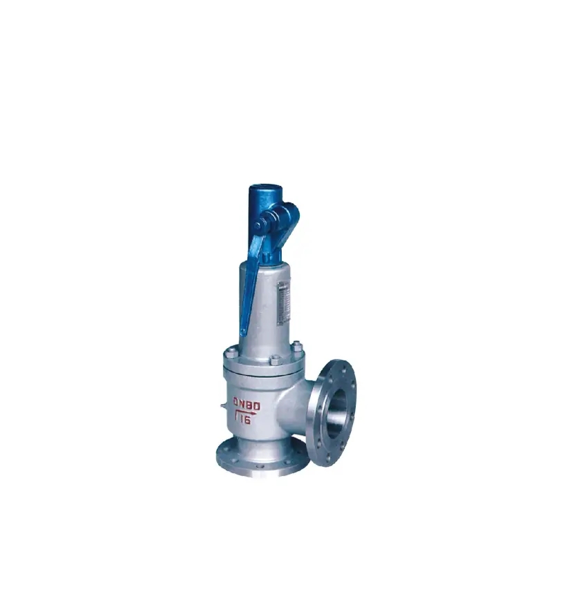
Type A44C - Safety Valve
Safety Valves, angle type
Full lift safety valve
Standard safety valve for fluids
Metal to metal seated, with lifting device,
Inlet: Flanged connection acc. to ANSI B16.5
Outlet: Flanged connection acc. to ANSI B16.5
Closed bonnet
Applications:
Provided as safety device for protection against excessive pressure in pressure vessels.
Approved for gases, vapours and fluids.
Working temperatures:
-60°C up to +200°C for stainless steel material
-29°C up to 300°C for cast steel material
Standards Compliance:
Design and Manufacture: API RP 520
Face to Face(end to end): API 526
Test and Inspection: API 527
Main property specifiecation
| Mormal Pressure |
PN |
150 |
300 |
600 |
900 |
150 |
| Body strength |
Ps(Mpa) |
3.0 |
7.5 |
15 |
22.5 |
38 |
| Set pressure |
Pk(Mpa) |
0.1-2 |
1.6-5 |
3.2-10 |
8-25 |
10-25 |
| Seal pressure |
Pm(Mpa) |
90%Pk |
| Reseation pressure |
Ph(Mpa) |
≥90%Pk |
| Relieving Pressure |
Pp(Mpa) |
≤1.1Pk |
| Lift height |
H(mm) |
≥1/4 d0 |
| Appropriate temp. |
C (WCB) P, R (SS304, SS316) |
≤300℃ ≤200℃ |
| Appropriate Medium |
C (WCB) P, R (SS304, SS316) |
Gsa, Liquid Corrosive medium |
Code of throat diameter
| Code |
Diameter |
Code |
Diameter |
| D |
10 |
L |
20 |
| E |
13 |
M |
55 |
| F |
16 |
N |
60 |
| G |
20.5 |
P |
72 |
| H |
26 |
Q |
96 |
| J |
33 |
R |
115 |
| K |
40 |
T |
148 |
Main Dimensions
| A44C150 |
| Nominal Diameter (in) |
Dimensions(mm) Inlet flange 150Lb |
| d0 |
D |
D1 |
D2 |
b |
t |
Z-Φd |
DN' |
D' |
D1' |
D2' |
b' |
t |
Z'-Φd' |
L |
L1 |
H |
| 1/2" x 3/4" |
D |
89 |
60.5 |
35 |
12 |
5 |
4-15 |
20 |
98 |
70 |
43 |
14 |
1.6 |
4-15 |
90 |
90 |
260 |
| 3/4" x 1" |
D |
98 |
70 |
43 |
14 |
5 |
4-15 |
25 |
108 |
79.5 |
51 |
15 |
1.6 |
4-15 |
96 |
92 |
260 |
| 1" x 11/2" |
D |
108 |
79.5 |
51 |
15 |
5 |
4-15 |
40 |
127 |
98.5 |
73 |
18 |
1.6 |
4-15 |
115 |
105 |
280 |
| 1" x 2" |
D |
108 |
79.5 |
51 |
15 |
5 |
4-15 |
50 |
152 |
120.5 |
92 |
18 |
1.6 |
4-19 |
115 |
105 |
280 |
| 11/2" x 2" |
G |
127 |
98.5 |
73 |
18 |
5 |
4-15 |
50 |
152 |
120.5 |
92 |
18 |
1.6 |
4-19 |
121 |
124 |
310 |
| 11/2" x 21/2" |
G |
127 |
98.5 |
73 |
18 |
5 |
4-15 |
65 |
178 |
139.5 |
105 |
20 |
1.6 |
4-19 |
121 |
124 |
310 |
| 11/2" x3" |
G |
127 |
98.5 |
73 |
18 |
5 |
4-15 |
80 |
190 |
152.5 |
127 |
22 |
1.6 |
4-19 |
124 |
130 |
310 |
| 2" x21/2" |
H |
152 |
120.5 |
92 |
18 |
5 |
4-19 |
65 |
178 |
139.5 |
105 |
20 |
1.6 |
4-19 |
124 |
130 |
350 |
| 2" x 3" |
J |
152 |
120.5 |
92 |
18 |
5 |
4-19 |
80 |
190 |
152.5 |
127 |
22 |
1.6 |
4-19 |
124 |
130 |
350 |
| 21/2" x 4" |
J |
178 |
139.5 |
105 |
20 |
5 |
4-19 |
100 |
229 |
190.5 |
157 |
24 |
1.6 |
8-19 |
143 |
137 |
430 |
| 3" x 4" |
L |
190 |
152.5 |
127 |
22 |
5 |
4-19 |
100 |
229 |
190.5 |
157 |
24 |
1.6 |
8-19 |
162 |
156 |
490 |
| 4" x 6" |
N |
229 |
190.5 |
157 |
24 |
10 |
8-19 |
150 |
279 |
241.5 |
216 |
26 |
1.6 |
8-22 |
210 |
197 |
610 |
| 6" x 8" |
P |
279 |
241.5 |
216 |
26 |
10 |
8-22 |
200 |
343 |
298.5 |
270 |
29 |
1.6 |
8-22 |
241 |
240 |
840 |
| 8" x10" |
R |
343 |
298.5 |
270 |
29 |
10 |
8-22 |
250 |
406 |
362 |
324 |
31 |
1.6 |
12-25 |
279 |
276 |
990 |
| 12" x14" |
T |
483 |
432 |
381 |
32 |
10 |
12-25 |
350 |
533 |
476 |
413 |
35 |
1.6 |
12-29 |
370 |
360 |
1040 |
Remark: 150Lb for outlet flange
| A44C300, A44C300R |
| Nominal Diameter (in) |
Dimensions(mm) Inlet flange 300Lb |
| d0 |
D |
D1 |
D2 |
b |
t |
Z-Φd |
DN' |
D' |
D1' |
D2' |
b' |
t |
Z'-Φd' |
L |
L1 |
H |
| 1/2" x 3/4" |
D |
95 |
66.5 |
35 |
15 |
5 |
4-15 |
20 |
98 |
70 |
43 |
14 |
1.6 |
4-15 |
90 |
90 |
260 |
| 3/4" x 1" |
D |
117 |
82.5 |
43 |
16 |
5 |
4-19 |
25 |
108 |
79.5 |
51 |
15 |
1.6 |
4-15 |
96 |
92 |
260 |
| 1" x 11/2" |
D |
124 |
89 |
51 |
18 |
5 |
4-19 |
40 |
127 |
98.5 |
73 |
18 |
1.6 |
4-15 |
115 |
105 |
280 |
| 1" x 2" |
D |
124 |
89 |
51 |
18 |
5 |
4-19 |
50 |
152 |
120.5 |
92 |
18 |
1.6 |
4-19 |
115 |
105 |
295 |
| 11/2" x 2" |
F |
156 |
114.5 |
73 |
20 |
5 |
4-22 |
50 |
152 |
120.5 |
92 |
18 |
1.6 |
4-19 |
121 |
124 |
310 |
| 11/2" x 21/2" |
F |
156 |
114.5 |
73 |
20 |
5 |
4-22 |
65 |
178 |
139.5 |
105 |
20 |
1.6 |
4-19 |
121 |
124 |
310 |
| 11/2" x3" |
F |
156 |
114.5 |
73 |
20 |
5 |
4-22 |
80 |
190 |
152.5 |
127 |
22 |
1.6 |
4-19 |
124 |
130 |
310 |
| 2" x21/2" |
H |
165 |
127 |
92 |
22 |
5 |
8-19 |
65 |
178 |
139.5 |
105 |
20 |
1.6 |
4-19 |
124 |
130 |
350 |
| 2" x 3" |
H |
165 |
127 |
92 |
22 |
5 |
8-19 |
80 |
190 |
152.5 |
127 |
22 |
1.6 |
4-19 |
124 |
130 |
350 |
| 21/2" x 4" |
J |
190 |
149 |
105 |
24 |
5 |
8-22 |
100 |
229 |
190.5 |
157 |
24 |
1.6 |
8-19 |
143 |
137 |
430 |
| 3" x 4" |
L |
210 |
168.5 |
127 |
28 |
5 |
8-22 |
100 |
229 |
190.5 |
157 |
24 |
1.6 |
8-19 |
162 |
156 |
490 |
| 4" x 6" |
N |
254 |
200 |
157 |
32 |
10 |
8-22 |
150 |
279 |
241.5 |
216 |
26 |
1.6 |
8-22 |
210 |
197 |
610 |
| 6" x 8" |
P |
318 |
270 |
216 |
38 |
10 |
12-22 |
200 |
343 |
298.5 |
270 |
29 |
1.6 |
8-22 |
241 |
240 |
840 |
| 8" x10" |
R |
381 |
330 |
270 |
42 |
10 |
12-25 |
250 |
406 |
362 |
324 |
31 |
1.6 |
12-25 |
279 |
276 |
990 |
| 10" x12" |
T |
445 |
387.5 |
324 |
46 |
10 |
16-28 |
350 |
533 |
476 |
413 |
35 |
1.6 |
12-28 |
350 |
330 |
1040 |
Remark: 150Lb for outlet flange
| A44C600 |
| Nominal Diameter (in) |
Dimensions(mm) Inlet flange 600Lb |
| d0 |
D |
D1 |
D2 |
b |
t |
Z-Φd |
DN' |
D' |
D1' |
D2' |
b' |
t |
Z'-Φd' |
L |
L1 |
H |
| 3/4" x 1" |
D |
118 |
82.5 |
43 |
16 |
7 |
4-19 |
25 |
108 |
79.5 |
51 |
15 |
1.6 |
4-15 |
96 |
92 |
280 |
| 1" x 2" |
D |
124 |
89 |
51 |
19 |
7 |
4-19 |
50 |
152 |
120.5 |
92 |
18 |
1.6 |
4-19 |
115 |
105 |
300 |
| 11/2" x 2" |
F |
156 |
114.5 |
73 |
22 |
7 |
4-22 |
50 |
152 |
120.5 |
92 |
18 |
1.6 |
4-19 |
152 |
124 |
300 |
| 11/2" x 21/2" |
F |
156 |
114.5 |
73 |
22 |
7 |
4-22 |
65 |
178 |
139.5 |
105 |
20 |
1.6 |
4-19 |
152 |
124 |
330 |
| 11/2" x3" |
F |
156 |
114.5 |
73 |
22 |
7 |
4-22 |
80 |
190 |
152.5 |
127 |
22 |
1.6 |
4-19 |
152 |
124 |
330 |
| 2" x21/2" |
H |
165 |
127 |
92 |
26 |
7 |
8-19 |
65 |
178 |
139.5 |
105 |
20 |
1.6 |
4-19 |
162 |
154 |
330 |
| 2" x 3" |
H |
165 |
127 |
92 |
26 |
7 |
8-19 |
80 |
190 |
152.5 |
127 |
22 |
1.6 |
4-19 |
162 |
154 |
360 |
| 21/2" x 4" |
K |
190 |
149 |
100 |
29 |
7 |
8-22 |
100 |
229 |
190.5 |
157 |
24 |
1.6 |
8-19 |
143 |
165 |
360 |
| 3" x 4" |
K |
210 |
168 |
127 |
32 |
10 |
8-22 |
100 |
229 |
190.5 |
157 |
24 |
1.6 |
8-19 |
162 |
155 |
440 |
| 4" x 6" |
N |
273 |
216 |
157 |
38 |
10 |
8-25 |
150 |
279 |
241.5 |
216 |
26 |
1.6 |
8-22 |
210 |
200 |
610 |
| 6" x 8" |
P |
356 |
292 |
216 |
46 |
10 |
12-29 |
200 |
343 |
298.5 |
270 |
29 |
1.6 |
8-22 |
241 |
240 |
625 |
Remark: 150Lb for outlet flange
Materials for main parts
| NO |
Name of part |
Materials A44Y-C |
Materials A44Y-P |
Materials A44Y-R |
| 1 |
Body |
WCB |
304 |
316 |
| 2 |
Nozzle |
2Cr13/ 304 |
304 |
316 |
| 3 |
Adjusting Ring |
2Cr13/ 304 |
304 |
316 |
| 4 |
Disc |
2Cr13/ 304 |
304 |
316 |
| 5 |
Guide sleeve |
2Cr13/ 304 |
304 |
316 |
| 6 |
Bonnet |
ZG230-450 |
ZG230-450 |
ZG230-450 |
| 7 |
Spring |
50CrVA |
50CrVA coated teflon |
50CrVA coated teflon |
| 8 |
Stem |
2Cr13 |
304 |
316 |
| 9 |
Adjusting bolt |
45 |
2Cr13 |
2Cr13 |
| 10 |
Cap |
ZG200-400 |
ZG200-400 |
ZG200-400 |
| Sealing surface of material "H" depositing D507, "Y" depositing stellite |
Essential:
Valves are delivered at a set pressure, therefore when ordering
Please confirm set pressure, medium and temperature
TS
Safety accessory and Safety protection device
Manufacture License of Special Equipment, People's republic of China